Category: Antenna

  • How to Build a Copper J-Pole Antenna for HAM and GMRS Radio (DIY Step-by-Step Guide)

    How to Build a Copper J-Pole Antenna for HAM and GMRS Radio (DIY Step-by-Step Guide)


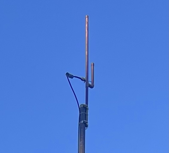
    If youโ€™ve ever felt the desire to construct your antenna yourself, only to be undecided on how to proceed, then you need to build a copper j-pole antenna and we think this project is for you. This is both cost-effective and requires little to no special equipment.

    The first antenna I made was a J-pole, and I didnโ€™t have an SWR meter for that project either. I just made my measurements, assembled the thing, plugged it in, and it worked wonderfully. This is, of course, the beauty of that design.

    At RadioOpBox.com, we enjoy radio projects that can be completed by anyone, regardless of their level of radio knowledge.


    ???? What Youโ€™ll Need

    Everything that you will need to build a copper j-pole antenna, you can purchase either at a hardware store or through the internet.

    Materials:

    • 10 ft of ยฝ inch copper pipe
    • Two ยฝ-inch copper T-fittings
    • One ยฝ inch copper end cap
    • Coax connector (SO-239 or N-type)
    • Stainless steel hose clamps
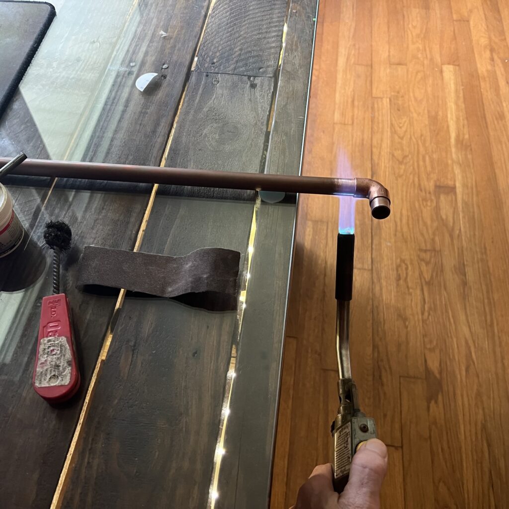
    • Solder or brazing torch
    • Measuring tape and hacksaw

    Recommended accessories:


    ???? Step 1: Understanding the J-Pole

    The J-pole antenna has a half-wave radiator and a quarter-wave matching stub. This simplifies the antenna construction process because it doesnโ€™t require a ground plane, only accurate measurements and adequate solder joints.

    For 2-meter HAM frequencies (~146 MHz):

    Long radiator: ~58 inches

    SHORT STUB: ~19 INCH

    For GMRS (462โ€“467 MHz) operation, reduce each dimension by one-third., reduce each dimension to about one-third.


    ??? **Step 2: Cut and Assemble**

    1. One copper pipe, cut to 58 inches.
    2. Trim another to 19 inches.
    3. Join them using a T-fitting at the bottom.
    4. Cap the top of the longer pipe.
    5. Leave approximately ยพ inch space between the two pipes.

    Dry fit first, then solder when satisfied with the design.


    ???? Step 3: Connect the Feedpoint

    Connect your coaxial cable feed line approximately 2ยฝ inches from the T-joint:

    • Center conductor โ†’ longer radiator
    • Shield โ†’ shorter stub

    Initially, you can start using hose clamps, then solder it permanently once itโ€™s functioning.


    # Step 4: Real-World Setup

    I didnโ€™t use any meters or analyzers, I just hooked it up to my radio, erected a mast, and keyered up. The difference was clear immediately. The signal from my local repeater came in stronger, and I was receiving clear reports from my contacts several miles away.

    The beauty of this design is that it is forgiving, simple, and can still produce wonderful results without using actual measurements.


    ???? Step 5: Mounting

    Try to install your antenna as high as possible, preferably 15 to 20 feet from the ground. An mast made from PVC or fiberglass will be your best option.

    If itโ€™s a matter of going outside, itโ€™s important to seal the joints and ground the coax.


    ???? What to Expect

    A properly constructed copper J-pole can provide you with:

    • Gain: ~3 dBi
    • VSWR: Preferably low enough to ensure reliability
    • Range: 15 to 30 miles line-of-sight (dependent upon terrain and radio

    Pair it with a good handheld like the
    Anytone AT-D878UVII+
    and will notice a marked improvement in clarity and reach.


    # Final Thoughts

    One of the most satisfying amateur radio projects to undertake yourself is to build a copper J-Pole antenna of your own. Itโ€™s extremely low-cost, quick, and will provide superior results without having to use any additional electronics or analyzers.

    At RadioOpBox, we share how-to’s that range from real-world experience, the sort of thing that you can really build, not just read.

    If this guide has assisted you, support us by visiting our affiliates:

    Always keep exploring, experimenting, and 73!

    โ€“ The RadioOpBox Team


    Written by the RadioOpBox Team โ€” a group of licensed operators and radio enthusiasts, sharing real world projects, tutorials, and reviews since 2025.


    Disclosure

    As an Amazon Associate and BTECH affiliate, RadioOpBox.com may earn commissions from qualifying purchases. These small commissions help us keep creating free, hands-on guides for radio enthusiasts. Thanks for your support!
  • Building Your First GMRS Base Station

    Building Your First GMRS Base Station

    Getting Started with GMRS

    If you’ve wondered how to make a GMRS base station, you’re in the right location. Constructing your own base station is one of the finest ways to extend communication range, reliability, and clarity for local or emergency purposes. If you are new to GMRS or looking to upgrade from a handheld radio, this guide will show you exactly how to build your installation step by step.

    A GMRS base station makes you stay in touch with your group, household, or emergency contacts even when cell networks fail โ€” and the good news is that you can build one using some crucial components.


    The Key Components of a GMRS Base Station

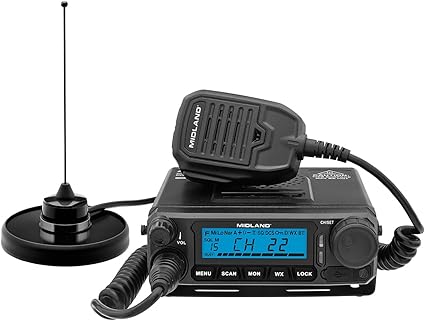
    Midland MXT500 MicroMobile 50-Watt GMRS Radio - How to Build a GMRS Base Station

    Building your own first GMRS base station is easier than you think once you have the right components.


    1. GMRS Base Radio

    Your radio is the hub of your station. It determines the power you will be able to transmit and what features you will be able to use (such as repeater access or channel scanning).

    Radios We Recommend:

    Midland MXT500 MicroMobile 50-Watt GMRS Radio โ€“ a high-powered, easy-to-use GMRS base radio perfect for beginners. BTECH GMRS-50X1 50-Watt GMRS Base Radio โ€“ advanced programming features, repeater support.

    Tip: For even more flexibility, check out our Frequency Programming guide to GMRS and HAM Radios.


    2. Antenna and Coax Cable

    The antenna is the deal-breaker unit of your GMRS base station range. Putting your antenna up high (on your roof or pole) provides you with improved line-of-sight and greater reach.

    Recommended Antennas:

    Nagoya TB-320A Base Antenna for GMRS โ€” very low cost, easy to install, and works very well for home setups.

    Comet GP-9 Dual Band Base Antenna โ€” great gain and life.

    For the best performance, use low-loss coax cable like LMR-400 Coax Cable run from your antenna to your radio.

    Related Reading: Best Accessories for Two-Way Radios


    3. Power Supply

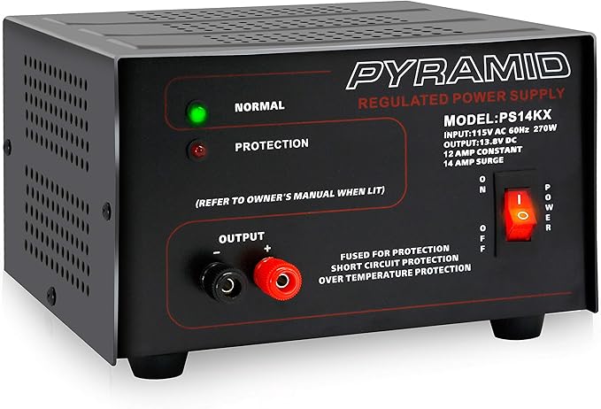
    Pyramid PS14KX 12V Power Supply

    Most GMRS base radios use 12V DC power, which means youโ€™ll need a reliable converter or power supply if youโ€™re running it from your home outlet.

    Recommended Power Supply:

    Pyramid PS14KX 12V Power Supply โ€” provides stable current for long operating sessions.

    If you want a stronger setup which can survive non-outages, include a solar backup or battery system. We discuss this in detail in our Emergency Power Options for HAM Operators guide.


    4. Mounting, Grounding & Safety

    Donโ€™t skip grounding โ€” itโ€™s essential for lightning safety and reducing interference. Ground both your radio and your antenna system properly.

    Don’t omit grounding โ€” it is required to keep you safe from lightning and to reduce interference. Ground both your radio and your antenna system properly.

    For safety tips, see our guide on Lightning and Antenna Safety Tips.


    How to Assemble Your GMRS Base Station

    Here’s step by step how to assemble your GMRS base station:

    Mount your antenna as high as it will go safely (roof, pole, or tower).

    Connect your antenna to your radio with low-loss coax.

    Connect your power source to your GMRS radio.

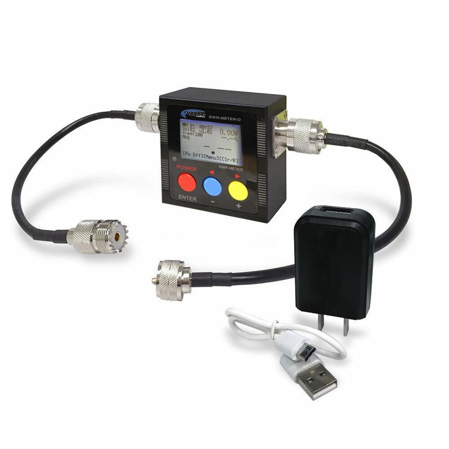
    Tune your antenna with an SWR meter for optimal performance.

    Do a range test to make sure your setup is transmitting cleanly.

    Following assembly, your GMRS base station gives you sharp communication across several miles โ€” perfect for community nets, prepping, or off-grid communications.


    Pro Tips for Expanding Your Setup

    Once you’ve got your base station operational, you can expand it with ease by adding:

    Repeater Access: to boost your range of communication.

    External Speaker: for improved indoor clarity.

    Battery Backup: for continuous off-grid use.

    Check out our article on Essential Two-Way Radio Accessories for Enhanced Communication additional tips on how to make your set-up better.


    Final Thoughts

    With what you’ve just read about how to build a GMRS base station, you’re now ready to have access to powerful, solid communications that beat handhelds every time. With the right radio, antenna, and power setup, you’ll have a station that keeps you in touch โ€” whether it’s for everyday use, emergency preparedness, or communicating with your neighborhood.

    Start constructing today and watch what a good-quality GMRS base station can achieve!


    Amazon Affiliate Disclosure

    I am an Amazon Associate and earn commissions from qualifying purchases. That means if you click on a product link and purchase something, we’ll receive a small commission at no extra cost to you. This helps support our content at RadioOpBox.com โ€” thank you for the support!

  • Preventing Water Damage to Your Antenna and SWR Meter

    Preventing Water Damage to Your Antenna and SWR Meter

    For amateur radio enthusiasts and CB radio operators, maintaining a clear and strong signal is paramount. This relies heavily on two critical pieces of equipment: your antenna and your SWR meter. While we often focus on their technical performance, a silent threat can quietly degrade both: water. Moisture intrusion, particularly at the vulnerable connection points between your antenna mount and your SWR meter, can lead to inaccurate readings, signal loss, and costly equipment failure. Protecting these components isnโ€™t just about performanceโ€”itโ€™s about safeguarding your investment and ensuring years of reliable communication.


    Protecting Your Antennaโ€™s Connection Points

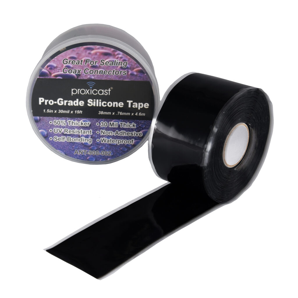
    PRX WPT Black 30 Case Tape 3000 2e2e pg

    Your antennaโ€™s connection points are the first line of defense against the elements. The coaxial cable connector at the antenna base is constantly exposed to rain, snow, and humidity. When water seeps into these connections, it initiates corrosion on the metal surfaces. This corrosion creates a high-resistance path that disrupts the RF signal traveling to and from your antenna. The result is decreased performance, higher SWR readings, and potentially permanent damage to the connector itself.

    The most effective and affordable way to prevent this is by using high-quality coax seal tape or butyl rubber tape. This stretchy, malleable tape is specifically designed for weatherproofing electrical connections.

    How to use:

    1. Ensure the connector is hand-tight plus a quarter turn with a wrench for a solid mechanical connection.
    2. Stretch the tape and wrap it tightly around the connector and the cable itself, working up the cable to create a watertight seal.

    Recommended Product:

    For an even more robust solution, consider heat shrink tubing with internal sealant. When heated, it shrinks to form a tight seal while the adhesive melts to encapsulate the connection, blocking moisture. Combine this with a UV-resistant coaxial drip loop, a simple slack loop in the cable installed just before entry into your vehicle or house, which forces water to drip off the bottom of the loop instead of traveling along the cable.

    Recommended Product:


    Safeguarding Your SWR Meter from Moisture

    9 Unusual Ways for Using Silica Gel Packets

    While your antenna is outside, your SWR meter is also highly susceptible to moisture damage, often via the coaxial cables themselves. Water can travel along the inside of the coaxial braid, a phenomenon called โ€œcable wicking,โ€ and seep into your SWR meter, causing inaccurate readings, internal corrosion, and complete meter failure.

    Prevention Tips:

    • Seal all outdoor connections as previously described.
    • Avoid placing a cool SWR meter in a warm, humid environment, which can cause condensation inside the unit.
    • Ensure PL-259 connectors are properly soldered and crimped.
    • Use rubber port cover caps to protect unused meter ports.
    • For meters in enclosed spaces, a small packet of silica gel desiccant helps control humidity.

    Recommended Products:


    A little preventative maintenance goes a long way in radio operation. By properly sealing your antennaโ€™s connection points and managing your SWR meterโ€™s environment, you effectively block moisture. These simple, low-cost steps will ensure your equipment provides accurate readings and optimal performance for years to come. Remember: a dry connection is a clear connection.


    Amazon Affiliate Disclosure

    Some of the links in this article are affiliate links. This means that at no extra cost to you, I may earn a small commission if you click through and make a purchase. This helps support the site and allows me to continue creating content like this. I only recommend products that I believe are high-quality and valuable for my readers.